Decoding the Language of Hydraulics: A Comprehensive Guide to Directional Control Valve Symbols (PDF)
In the intricate world of hydraulic systems, understanding the language of symbols is paramount. These symbols, meticulously standardized, act as a universal shorthand, enabling engineers and technicians worldwide to design, troubleshoot, and maintain complex machinery with precision. This article delves into the critical realm of directional control valve symbols, providing a comprehensive guide to understanding their meaning and application. We will explore the importance of these symbols, how to interpret them, and where to find readily available resources, including the coveted directional control valve symbols PDF, essential for any professional or enthusiast in the field.
The Importance of Standardization in Hydraulics
Hydraulic systems are the lifeblood of countless industries, from construction and manufacturing to aerospace and agriculture. The power, precision, and reliability they offer are unparalleled. However, the complexity of these systems necessitates a common language. This is where standardization comes into play. The International Organization for Standardization (ISO) and the National Fluid Power Association (NFPA) have established comprehensive standards for hydraulic symbols, ensuring consistency and clarity across the globe. This standardization minimizes errors, facilitates collaboration, and enhances safety.
What are Directional Control Valves and Why are Their Symbols Crucial?
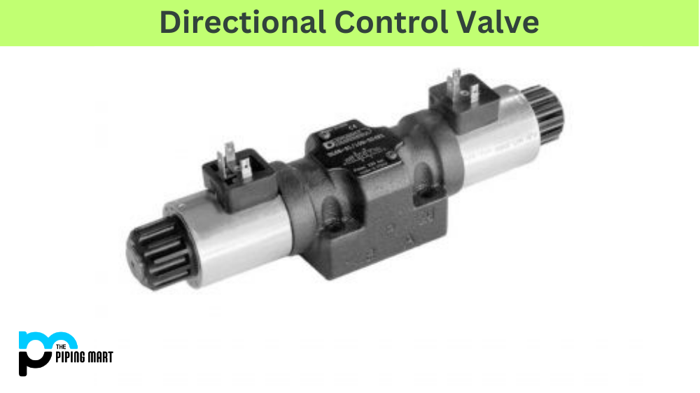
Directional control valves (DCVs) are the gatekeepers of hydraulic systems. They direct the flow of hydraulic fluid, controlling the movement of actuators (cylinders and motors). These valves are responsible for starting, stopping, and changing the direction of motion, making them fundamental components in any hydraulic circuit. The symbols used to represent these valves in schematics are, therefore, of utmost importance. Accurate interpretation of directional control valve symbols is crucial for understanding the function of a hydraulic system, diagnosing malfunctions, and ensuring proper operation.
Breaking Down the Symbols: A Guide to Understanding the Basics
Directional control valve symbols are typically represented by a series of interconnected squares. Each square represents a valve’s position, and the lines and arrows within the squares depict the flow paths of the hydraulic fluid. Understanding these components is key to deciphering the overall function of the valve.
- Valve Positions: The number of squares indicates the number of valve positions. A two-position valve has two squares, representing two possible states, while a three-position valve has three squares.
- Ports: Ports are the connections to the valve, typically labeled with letters like P (pressure), T (tank), A and B (actuator ports). These ports are represented by lines extending from the squares.
- Flow Paths: Arrows within the squares indicate the direction of fluid flow. Solid lines represent flow paths when the valve is in a specific position.
- Valve Actuation: Symbols indicate how the valve is actuated, such as by a solenoid, a spring, or manually.
Mastering these basic elements is the first step toward understanding the more complex directional control valve symbols.
Common Directional Control Valve Configurations and Their Symbols
The variety of directional control valves available is vast, each designed for specific applications. However, certain configurations are more common than others. Understanding these common types and their corresponding symbols is essential for anyone working with hydraulic systems.
- 2/2 Valve (Two-Position, Two-Way): This valve has two positions and two ports. It can either block the flow or allow it to pass through.
- 3/2 Valve (Three-Position, Two-Way): This valve has three positions and two ports. It can direct flow in one direction, block it, or direct it in the opposite direction.
- 4/2 Valve (Four-Position, Two-Way): This valve has four positions and two ports. It’s often used for more complex control scenarios.
- 4/3 Valve (Four-Position, Three-Way): This is the most common configuration, offering versatility in controlling actuators.
Recognizing these configurations and their associated directional control valve symbols is key to quickly understanding a hydraulic circuit’s functionality.
Finding Resources: The Value of a Directional Control Valve Symbols PDF
For easy reference and in-depth learning, a directional control valve symbols PDF is an invaluable resource. These PDFs typically contain comprehensive charts, diagrams, and explanations of various directional control valve symbols. They are often available for free download from reputable sources, such as hydraulic component manufacturers and educational institutions.
A well-structured directional control valve symbols PDF will often include:
- A complete list of symbols: Covering a wide range of valve types and functionalities.
- Detailed explanations: Describing each symbol’s meaning and application.
- Illustrative diagrams: Showing how symbols are used in actual hydraulic circuits.
- Examples of different valve configurations: Providing practical understanding.
Having a readily accessible directional control valve symbols PDF can significantly streamline the learning process, improve troubleshooting efficiency, and enhance the overall understanding of hydraulic systems.
How to Use a Directional Control Valve Symbols PDF Effectively
To maximize the benefits of a directional control valve symbols PDF, consider these tips:
- Familiarize yourself with the basics: Before diving into complex symbols, ensure you understand the fundamental concepts outlined earlier in this article.
- Use it as a reference: Don’t try to memorize every symbol. Instead, use the PDF as a quick reference guide while working on hydraulic circuits or studying schematics.
- Practice: The best way to learn is through practice. Use the PDF to analyze real-world hydraulic circuits and identify the various directional control valve symbols.
- Supplement with other resources: The PDF is a valuable tool, but it should be supplemented with other learning materials, such as textbooks, online courses, and hands-on experience.
- Stay Updated: Hydraulic technology evolves. Ensure your PDF is up-to-date with the latest standards and symbol revisions.
Troubleshooting with Directional Control Valve Symbols
When troubleshooting hydraulic systems, the ability to read and interpret directional control valve symbols is crucial. By analyzing the schematic and understanding the function of each valve, technicians can quickly pinpoint the source of a problem. For example, if an actuator is not moving, examining the directional control valve symbols in the circuit can reveal whether the valve is correctly directing the flow of fluid. This allows for a systematic approach to troubleshooting, saving time and minimizing downtime.
Here’s a simplified troubleshooting scenario:
- Observe the Problem: The cylinder isn’t extending.
- Review the Schematic: Identify the directional control valve controlling the cylinder’s extension.
- Analyze the Symbol: Determine the valve’s position and expected flow paths when activated.
- Check for Actuation: Verify if the valve is receiving the correct signal to change positions.
- Inspect the Valve: If the signal is correct, the valve itself might be faulty, and will need inspection or replacement.
This systematic process, guided by the directional control valve symbols in the schematic, is a cornerstone of effective hydraulic troubleshooting.
Safety Considerations and Directional Control Valves
Hydraulic systems operate under high pressure, making safety paramount. Understanding directional control valve symbols is directly linked to safety. Incorrect interpretation or misapplication of these symbols can lead to dangerous situations, including uncontrolled movement of machinery, leaks, and equipment failure. Always adhere to safety guidelines and use appropriate personal protective equipment (PPE) when working with hydraulic systems. Proper understanding of the directional control valve symbols ensures that systems are designed and maintained to operate safely.
Beyond the Basics: Advanced Applications
The principles of directional control valve symbols extend to more complex applications, including proportional valves, servo valves, and electrohydraulic systems. These advanced systems utilize sophisticated control strategies, but the underlying principles of fluid flow and valve actuation remain the same. Understanding the basic directional control valve symbols provides a strong foundation for understanding these advanced applications. This includes understanding how different symbols represent the various control mechanisms within the valves.
Conclusion: Mastering the Language of Hydraulics
The ability to read and interpret directional control valve symbols is a fundamental skill for anyone working with hydraulic systems. From the basic understanding of valve positions and flow paths to the ability to troubleshoot complex circuits, this knowledge is essential. Utilizing resources like a directional control valve symbols PDF and consistently practicing will allow anyone to excel in this field. By embracing the universal language of hydraulic symbols, you can unlock the full potential of these powerful and versatile systems. Consider exploring the NFPA and ISO standards for deeper understanding and accuracy. Remember that continuous learning and practice are key to mastering the intricacies of hydraulic systems and the directional control valve symbols that define them.
[See also: Hydraulic Cylinder Troubleshooting Guide]
[See also: Understanding Hydraulic Pump Symbols]
[See also: Hydraulic Circuit Design Best Practices]

